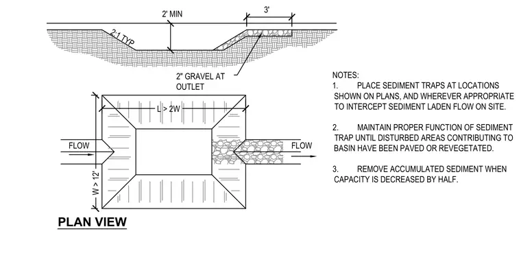
A sediment trap excavation features a minimum two-foot depth with two-to-one typical side slopes and a length greater than twice the width. The basin width is greater than twelve feet with incoming and outgoing water flow directions. Two-inch gravel is placed at the outlet structure with a three-foot transition zone. Notes specify placement locations on site, ongoing maintenance until upstream areas are paved or revegetated, and sediment removal when capacity is halved.
NOTES: 1. PLACE SEDIMENT TRAPS AT LOCATIONS SHOWN ON PLANS, AND WHEREVER APPROPRIATE TO INTERCEPT SEDIMENT LADEN FLOW ON SITE. 2. MAINTAIN PROPER FUNCTION OF SEDIMENT TRAP UNTIL DISTURBED AREAS CONTRIBUTING TO BASIN HAVE BEEN PAVED OR REVEGETATED. 3. REMOVE ACCUMULATED SEDIMENT WHEN CAPACITY IS DECREASED BY HALF. 2" GRAVEL AT OUTLET L > 2W W > 12' 2:1 TYP 2' MIN 3' FLOW FLOW PLAN VIEW
Members view this detail in full resolution, download the CAD files (SVG, PDF), and can adapt it in the built-in CAD editor — export DXF, DWG, or PDF.
Start membership