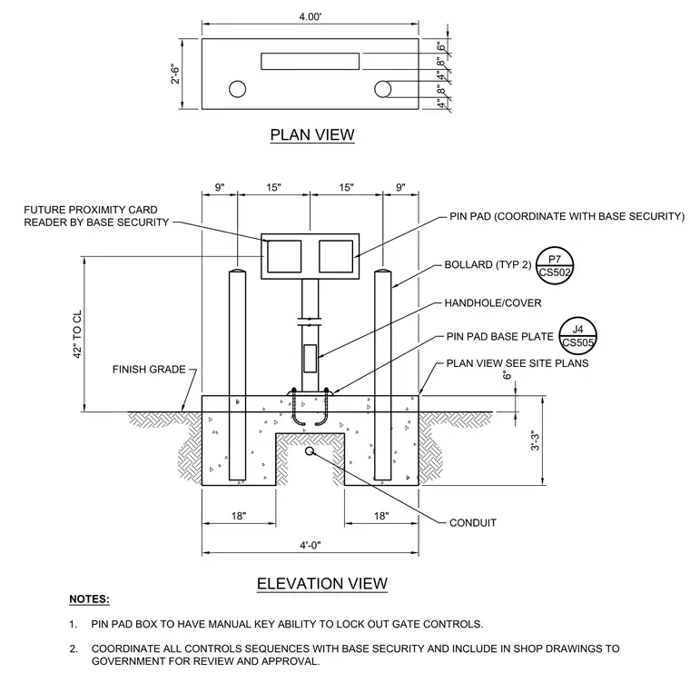
A reinforced concrete pad supports a center post equipped with a pin pad and future proximity card reader, flanked by two steel bollards anchored below finish grade. Underground electrical conduit routes through the center of the concrete foundation up into the pedestal. The pin pad mounting assembly includes a base plate secured to the concrete and a handhole with cover for access. Protection bollards are positioned symmetrically on either side of the control station at forty-two inches to centerline. All control sequences require coordination with base security and manual key capability for gate controls.
9" 15" 15" 9" 18" 18" 4'-0" 3'-3" 6" ELEVATION VIEW 4.00' 2'-6" PLAN VIEW 4" 8" 4" 8" 6" HANDHOLE/COVER BOLLARD (TYP 2) CONDUIT FINISH GRADE PIN PAD BASE PLATE PLAN VIEW SEE SITE PLANS FUTURE PROXIMITY CARD READER BY BASE SECURITY PIN PAD (COORDINATE WITH BASE SECURITY) CS502 P7 CS505 J4 NOTES: 1. PIN PAD BOX TO HAVE MANUAL KEY ABILITY TO LOCK OUT GATE CONTROLS. 2. COORDINATE ALL CONTROLS SEQUENCES WITH BASE SECURITY AND INCLUDE IN SHOP DRAWINGS TO GOVERNMENT FOR REVIEW AND APPROVAL. 42" TO CL
Members view this detail in full resolution, download the CAD files (SVG, PDF), and can adapt it in the built-in CAD editor — export DXF, DWG, or PDF.
Start membership