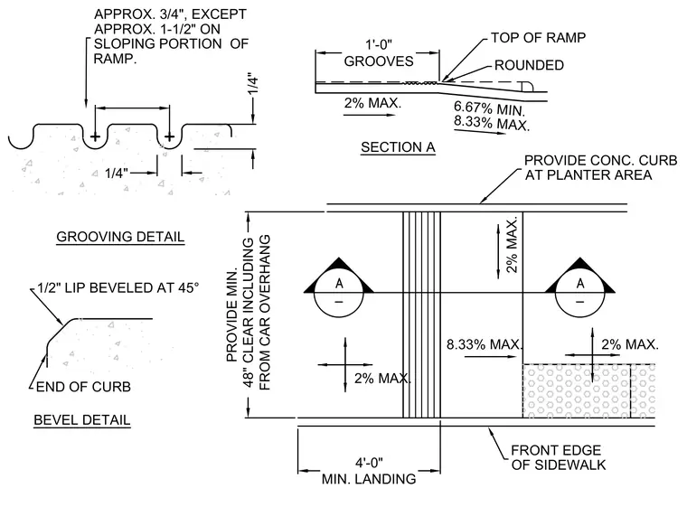
A concrete curb ramp assembly features specific dimensional and slope requirements. The main plan view contains a landing with a four-foot minimum dimension and a maximum cross slope of two percent, alongside a ramp section with slopes ranging from a minimum of 6.67 percent to a maximum of 8.33 percent. Supplementary details specify a concrete curb at the planter area, a rounded top of ramp transition, and a bevel detail featuring a one-half-inch lip beveled at forty-five degrees at the end of the curb. A grooving detail defines a one-foot-wide textured surface with quarter-inch grooves spaced approximately three-quarters of an inch apart, expanding to approximately one and one-half inches on the sloping portion of the ramp.
4'-0" MIN. LANDING 2% MAX. 2% MAX. 2% MAX. 8.33% MAX. 6.67% MIN. 8.33% MAX. GROOVING DETAIL BEVEL DETAIL SECTION A 2% MAX. PROVIDE MIN. 48" CLEAR INCLUDING FROM CAR OVERHANG 1/2" LIP BEVELED AT 45° END OF CURB APPROX. 3/4", EXCEPT APPROX. 1-1/2" ON SLOPING PORTION OF RAMP. FRONT EDGE OF SIDEWALK PROVIDE CONC. CURB AT PLANTER AREA TOP OF RAMP ROUNDED 1'-0" GROOVES 1/4" 1/4"
Members view this detail in full resolution, download the CAD files (SVG, PDF), and can adapt it in the built-in CAD editor — export DXF, DWG, or PDF.
Start membership