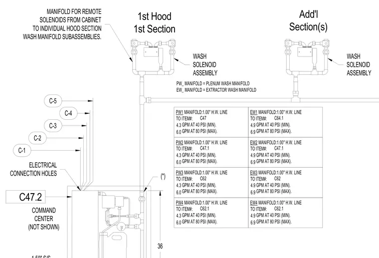
Remote solenoids extend from a cabinet to individual hood section wash manifold subassemblies, featuring plenum wash and extractor wash manifolds. The hot water lines connect to specific item numbers with defined flow rates at minimum 40 PSI and maximum 80 PSI pressures. Electrical connection holes are provided at the command center cabinet. The system connects the main manifold supply lines to individual wash solenoid assemblies and respective hood sections.
36 C-1 C-2 C-3 C-4 1st Hood 1st Section Add'l Section(s) C-5 MANIFOLD FOR REMOTE SOLENOIDS FROM CABINET TO INDIVIDUAL HOOD SECTION WASH MANIFOLD SUBASSEMBLIES. ELECTRICAL CONNECTION HOLES COMMAND CENTER (NOT SHOWN) WASH SOLENOID ASSEMBLY PW_ MANIFOLD = PLENUM WASH MANIFOLD EW_ MANIFOLD = EXTRACTOR WASH MANIFOLD WASH SOLENOID ASSEMBLY (*) PW1 MANIFOLD:1.00" H.W. LINE TO ITEM#: GPM AT 40 PSI (MIN). GPM AT 80 PSI (MAX). EW1 MANIFOLD:1.00" H.W. LINE TO ITEM#: GPM AT 40 PSI (MIN). GPM AT 80 PSI (MAX). PW2 MANIFOLD:1.00" H.W. LINE TO ITEM#: GPM AT 40 PSI (MIN). GPM AT 80 PSI (MAX). EW2 MANIFOLD:1.00" H.W. LINE TO ITEM#: GPM AT 40 PSI (MIN). GPM AT 80 PSI (MAX). PW3 MANIFOLD:1.00" H.W. LINE TO ITEM#: GPM AT 40 PSI (MIN). GPM AT 80 PSI (MAX). EW3 MANIFOLD:1.00" H.W. LINE TO ITEM#: GPM AT 40 PSI (MIN). GPM AT 80 PSI (MAX). PW4 MANIFOLD:1.00" H.W. LINE TO ITEM#: GPM AT 40 PSI (MIN). GPM AT 80 PSI (MAX). EW4 MANIFOLD:1.00" H.W. LINE TO ITEM#: GPM AT 40 PSI (MIN). GPM AT 80 PSI (MAX). C47.2 C47 4.3 6.0 C64.1 4.9 6.9 C47.1 4.3 6.0 C47.1 4.9 6.9 C62 4.3 6.0 C62 4.9 6.9 C62.1 4.3 6.0 C62.1 4.9 6.9
Members view this detail in full resolution, download the CAD files (SVG, PDF), and can adapt it in the built-in CAD editor — export DXF, DWG, or PDF.
Start membership