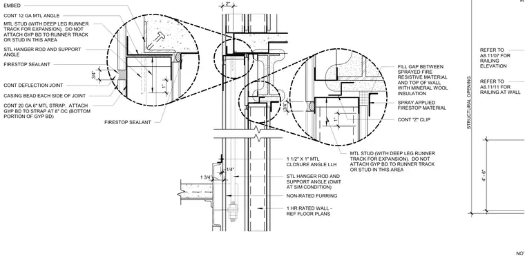
Intermediate landing support for a steel-framed stair system interfacing with a fire-rated partition. A steel hanger rod and support angle suspend the assembly, anchored to the structure above with an embed plate. Continuous metal studs with deep leg runner tracks accommodate vertical deflection, leaving gypsum board unattached at the joint to prevent binding. A continuous twenty-gauge metal strap and casing beads finish the deflection joint, which is sealed with firestop sealant. At the head of the wall, a continuous Z-clip and mineral wool insulation fill the gap beneath spray-applied fire-resistive material.
NOTE: REFER TO FLOOR PLANS FOR STAIR ORIENTATION. REFER TO A8.11/11 FOR RAILING AT WALL REFER TO A8.11/07 FOR RAILING ELEVATION STRUCTURAL OPENING 3" 4' - 6" FIRESTOP SEALANT MTL STUD (WITH DEEP LEG RUNNER TRACK FOR EXPANSION). DO NOT ATTACH GYP BD TO RUNNER TRACK OR STUD IN THIS AREA 3/4” 1” FIRESTOP SEALANT CONT DEFLECTION JOINT CASING BEAD EACH SIDE OF JOINT CONT 20 GA 6" MTL STRAP. ATTACH GYP BD TO STRAP AT 8" OC (BOTTOM PORTION OF GYP BD) CONT 12 GA MTL ANGLE 1/4" 1 3/4” STL HANGER ROD AND SUPPORT ANGLE 2" EMBED STL HANGER ROD AND SUPPORT ANGLE (OMIT AT SIM CONDITION) 1 1/2" X 1" MTL CLOSURE ANGLE LLH NON-RATED FURRING 1 HR RATED WALL - REF FLOOR PLANS 1” MTL STUD (WITH DEEP LEG RUNNER TRACK FOR EXPANSION). DO NOT ATTACH GYP BD TO RUNNER TRACK OR STUD IN THIS AREA CONT "Z" CLIP SPRAY APPLIED FIRESTOP MATERIAL FILL GAP BETWEEN SPRAYED FIRE RESISTIVE MATERIAL AND TOP OF WALL WITH MINERAL WOOL INSULATION 3/4”
Members view this detail in full resolution, download the CAD files (SVG, PDF), and can adapt it in the built-in CAD editor — export DXF, DWG, or PDF.
Start membership