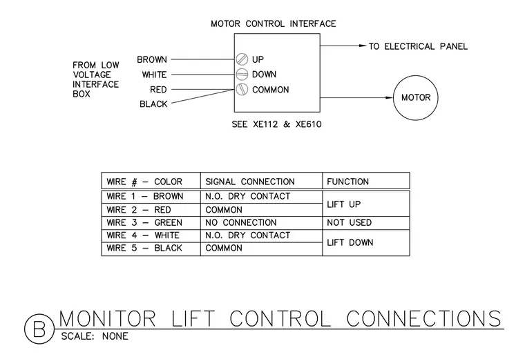
The motor control interface connects a low-voltage interface box to the motor and electrical panel using brown, white, red, and black wire connections labeled for up, down, and common functions. A detailed wire schedule lists wire numbers one through five with their respective colors, signal connections such as normally open dry contacts or common terminals, and functions for lift up and lift down operation.
Members view this detail in full resolution, download the CAD files (SVG, PDF), and can adapt it in the built-in CAD editor — export DXF, DWG, or PDF.
Start membership