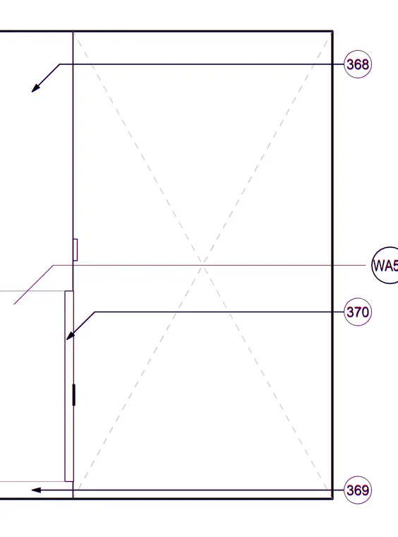
A vertical wall assembly is referenced by callout bubbles 368, 369, 370, and WA51. The framing or panel configuration is indicated with diagonal dashed lines representing an opening or cavity. Leader lines direct specific notes to the perimeter boundaries and interior layers of the assembly.
Members view this detail in full resolution, download the CAD files (SVG, PDF), and can adapt it in the built-in CAD editor — export DXF, DWG, or PDF.
Start membership