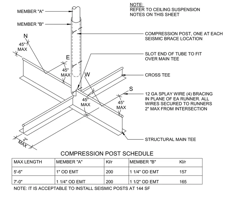
A compression post is installed at each seismic brace location with the tube end slotted to fit over the structural main tee. Four twelve-gauge splay wires provide bracing in the plane of each runner with all wires secured to runners within two inches maximum from the intersection. A compression post schedule lists maximum lengths of five feet six inches and seven feet zero inches using member A one-inch outer diameter electrical metallic tubing and member B one-quarter to one-half-inch outer diameter electrical metallic tubing with corresponding slenderness ratios. Seismic posts are acceptable to install at one hundred forty-four square feet.
NOTE: REFER TO CEILING SUSPENSION NOTES ON THIS SHEET COMPRESSION POST, ONE AT EACH SEISMIC BRACE LOCATION SLOT END OF TUBE TO FIT OVER MAIN TEE CROSS TEE 12 GA SPLAY WIRE (4) BRACING IN PLANE OF EA RUNNER. ALL WIRES SECURED TO RUNNERS 2" MAX FROM INTERSECTION STRUCTURAL MAIN TEE MAX LENGTH 5'-6" 7'-0" MEMBER "A" 1" OD EMT 1 1/4" OD EMT Kl/r 200 200 MEMBER "B" 1 1/4" OD EMT 1 1/2" OD EMT Kl/r 157 165 NOTE: IT IS ACCEPTABLE TO INSTALL SEISMIC POSTS AT 144 SF COMPRESSION POST SCHEDULE MEMBER "A" MEMBER "B" 45° MAX 45° MAX 45° MAX 45° MAX 2" MAX N E S W
Members view this detail in full resolution, download the CAD files (SVG, PDF), and can adapt it in the built-in CAD editor — export DXF, DWG, or PDF.
Start membership