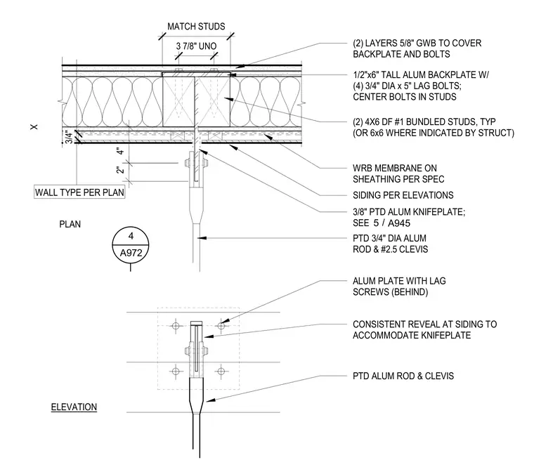
A painted three-eighths-inch aluminum knifeplate extends outward through the exterior siding to connect with a painted three-quarter-inch diameter aluminum rod and number two point five clevis. The knifeplate is secured behind the finish layer to a one-half-inch by six-inch tall aluminum backplate using four three-quarter-inch diameter by five-inch lag bolts centered in the wood stud framing. The backup support consists of two four-by-six Douglas Fir number one bundled studs, or six-by-six where indicated by structural drawings, wrapped in a water-resistive barrier membrane over exterior sheathing. Exterior siding features a consistent reveal to accommodate the knifeplate penetration. Two layers of five-eighths-inch gypsum wallboard cover the interior backplate and bolt assembly.
4" 2" X PLAN ELEVATION WRB MEMBRANE ON SHEATHING PER SPEC 1/2"x6" TALL ALUM BACKPLATE W/ (4) 3/4" DIA x 5" LAG BOLTS; CENTER BOLTS IN STUDS (2) 4X6 DF #1 BUNDLED STUDS, TYP (OR 6x6 WHERE INDICATED BY STRUCT) SIDING PER ELEVATIONS 3/8" PTD ALUM KNIFEPLATE; SEE PTD 3/4" DIA ALUM ROD & #2.5 CLEVIS ALUM PLATE WITH LAG SCREWS (BEHIND) CONSISTENT REVEAL AT SIDING TO ACCOMMODATE KNIFEPLATE PTD ALUM ROD & CLEVIS WALL TYPE PER PLAN (2) LAYERS 5/8" GWB TO COVER BACKPLATE AND BOLTS MATCH STUDS 3 7/8" UNO 3/4" 4 A972 / 5 A945
Members view this detail in full resolution, download the CAD files (SVG, PDF), and can adapt it in the built-in CAD editor — export DXF, DWG, or PDF.
Start membership