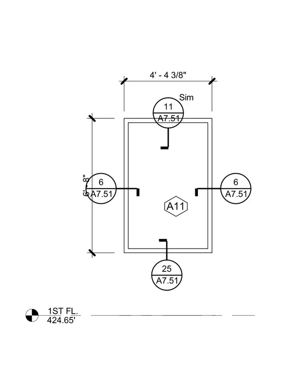
The drawing illustrates a rectangular plan detail measuring 4 feet 4 3/8 inches wide with internal framing or structural members. It features multiple section/detail reference tags (A7.51 bubbles 11, 6, and 25) along with a hexagon marker A11 and a first floor elevation of 424.65 feet. Dimensions define the boundaries and placement within the floor slab assembly.
1ST FL. 424.65' A11 6' - 8" 4' - 4 3/8" 6 A7.51 6 A7.51 11 A7.51 Sim 25 A7.51
Members view this detail in full resolution, download the CAD files (SVG, PDF), and can adapt it in the built-in CAD editor — export DXF, DWG, or PDF.
Sign in to subscribe