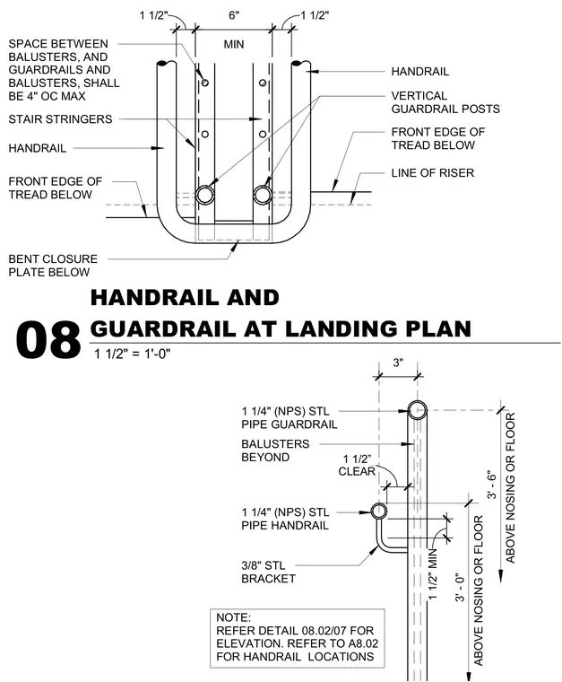
A steel pipe handrail and guardrail assembly is mounted at a stair landing. The one and one-quarter inch nominal pipe size steel pipe handrail is supported by a three-eighths inch steel bracket, maintaining a one and one-half inch clear space from the vertical guardrail posts. The guardrail stands three feet six inches above the nosing or floor, while the handrail is positioned three feet above the nosing or floor. Balusters and guardrail components maintain a maximum spacing of four inches on center. Stair stringers and a bent closure plate are positioned below the tread and riser lines.
CLEAR 1 1/2” 3" 3/8" STL BRACKET BALUSTERS BEYOND 3' - 0" ABOVE NOSING OR FLOOR ABOVE NOSING OR FLOOR 3' - 6" 1 1/4" (NPS) STL PIPE HANDRAIL 1 1/4" (NPS) STL PIPE GUARDRAIL 1 1/2" MIN NOTE: REFER DETAIL 08.02/07 FOR ELEVATION. REFER TO A8.02 FOR HANDRAIL LOCATIONS 1 1/2" MIN 6" 1 1/2" HANDRAIL VERTICAL GUARDRAIL POSTS SPACE BETWEEN BALUSTERS, AND GUARDRAILS AND BALUSTERS, SHALL BE 4" OC MAX FRONT EDGE OF TREAD BELOW LINE OF RISER STAIR STRINGERS HANDRAIL FRONT EDGE OF TREAD BELOW BENT CLOSURE PLATE BELOW 1 1/2" = 1'-0" 08 HANDRAIL AND GUARDRAIL AT LANDING PLAN
Members view this detail in full resolution, download the CAD files (SVG, PDF), and can adapt it in the built-in CAD editor — export DXF, DWG, or PDF.
Start membership