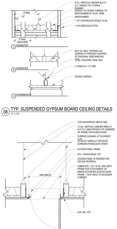
An access door is installed within a suspended gypsum board ceiling supported by a steel framing grid. The assembly utilizes an eighteen-gauge minimum one-and-one-half-inch metal frame fabricated for the attachment of the manufacturer's access door frame, which is tack welded to the adjacent cross furring. The ceiling grid consists of main runners, cross furring, and sixteen-gauge continuous perimeter angles secured with sheet metal screws. Twelve-gauge vertical hanger wires spaced at four feet on center and within six inches of corners support the access door frame, supplemented by two splay wires at opposite corners. Gypsum board finishes the ceiling assembly with standard metal casing beads at the access opening edges.
8" MAX EACH SIDE 6" MAX. 8 GA. VERTICAL HANGER @ 4'-0" O.C. SADDLE TIE TO MAIN RUNNER SADDLE TIE CROSS FURRING TO MAIN RUNNER W/ 16 GA. WIRE MAIN RUNNER 1 1/2" CONTINUOUS ANGLE 16 GA. 1 1#10 SMS EACH STUD #8 X 3/4" SELF TAPPING S.M. SCREWS TO PREVENT SLIPPING OF DIAGONAL WIRE BRACING. TYP. 12 GA. DIAGONAL WIRE TIES 4 TURNS IN 1 1/2" MIN. CROSS FURRING C B A PERIMETER PERIMETER INTERMEDIATE 1/2" PER SPECS FOR ANCHORAGE ABOVE SEE, 12 GA. VERTICAL HANGER WIRE AT 4'-0" O.C. AND WITHIN 6" OF CORNERS OF FRAME FOR ACESS DOOR FURRING CHANNEL ATTACHMENT CLIP (2) SPLAY WIRES AT OPPOSITE CORNERS FROM EACH OTHER ACCESS PANEL FRAME MTL. CASING BEAD TYP. ACCESS PANEL W/ RECESS FOR CEILING MATERIAL FABRICATE 1-1/2" 18 GA. MIN. MAT'L FRAME FOR ATTACHMENT OF MANUFACTURER'S ACCESS DOOR FRAME - TACK WELD TO ADJACENT FURRING GYP. BD. TYP. 3" = 1'-0" 08 TYP. SUSPENDED GYPSUM BOARD CEILING DETAILS
Members view this detail in full resolution, download the CAD files (SVG, PDF), and can adapt it in the built-in CAD editor — export DXF, DWG, or PDF.
Start membership