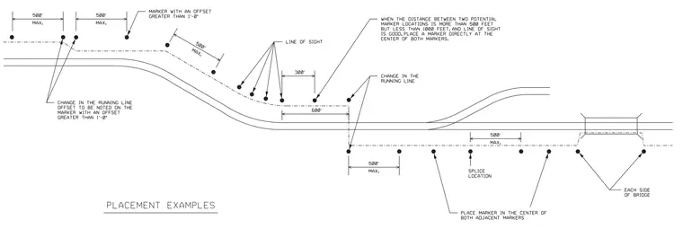
This diagram details the placement rules and spacing requirements for railway markers along running lines, changes in alignment, and bridge locations. Maximum spacing of 500 feet is specified for standard marker intervals, alongside specific placement criteria for line-of-sight conditions and running line changes. Splice locations and bridge approaches require designated marker positioning on each side of the bridge structure. Offsets greater than 1 foot must be specifically noted on the corresponding marker.
Members view this detail in full resolution, download the CAD files (SVG, PDF), and can adapt it in the built-in CAD editor — export DXF, DWG, or PDF.
Start membership