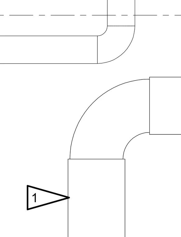
The image depicts a schematic layout of ductwork featuring 90-degree elbows and a center-line marking, along with a detail section marker numbered 1. The lines represent sheet metal duct transitions used in HVAC systems. It provides a simplified view of duct routing connections.
Members view this detail in full resolution, download the CAD files (SVG, PDF), and can adapt it in the built-in CAD editor — export DXF, DWG, or PDF.
Sign in to subscribe