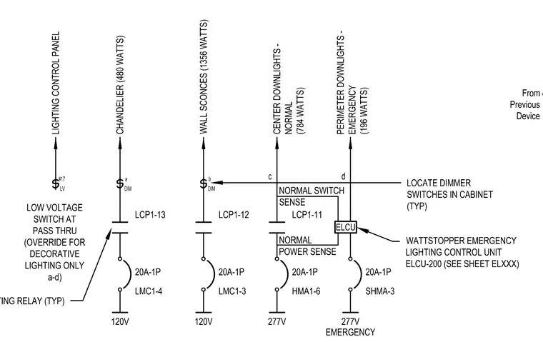
This diagram details the electrical wiring and relay connections for a lighting control system interfacing with various luminaire groups and control devices. The system connects a lighting control panel to a low-voltage pass-through override switch, a 480-watt chandelier circuit, a 1356-watt wall sconce circuit, a 784-watt normal center downlight circuit, and a 196-watt emergency perimeter downlight circuit. Each circuit incorporates typical lighting relays, twenty-amp single-pole circuit breakers, and specific panel circuit designations. An emergency lighting control unit, model ELCU-200, senses normal power and switches perimeter emergency downlights during a power loss. Dimmer switches are located within the cabinet typically, and low-voltage switches provide overrides for decorative lighting.
Members view this detail in full resolution, download the CAD files (SVG, PDF), and can adapt it in the built-in CAD editor — export DXF, DWG, or PDF.
Start membership