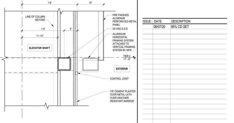
An exterior wall section details the sill condition of a prefinished aluminum perforated metal panel assembly at an elevator shaft. The cladding is supported by horizontal aluminum framing attached to a vertical framing system per manufacturer specifications, spanning past a hollow structural section. The backup wall consists of seven-eighths-inch cement plaster over metal lath and a weather-resistant barrier, featuring a control joint located below the steel tube. Dimensions indicate offsets from the column line and elevator shaft boundary.
TIER 2 11' - 6" PRE FINISHED ALUMINUM PERFORATED METAL PANEL ALUMINIUM HORIZONTAL FRAMING SYSTEM ATTACHED TO VERITCAL FRAMING SYSTEM BY MFR 7/8" CEMENT PLASTER OVER METAL LATH OVER WEATHER RESISTANT BARRIER 5X HSS S.S.D. CONTROL JOINT ELEVATOR SHAFT EXTERIOR 1'-1 1/2" 5" 1'-4" 10" 1'-9" LINE OF COLUMN BEYOND ISSUE: DATE: DESCRIPTION: 05/01/20 PERMIT READY SET ISSUE: DATE: DESCRIPTION: 08/07/20 95% CD SET
Members view this detail in full resolution, download the CAD files (SVG, PDF), and can adapt it in the built-in CAD editor — export DXF, DWG, or PDF.
Start membership