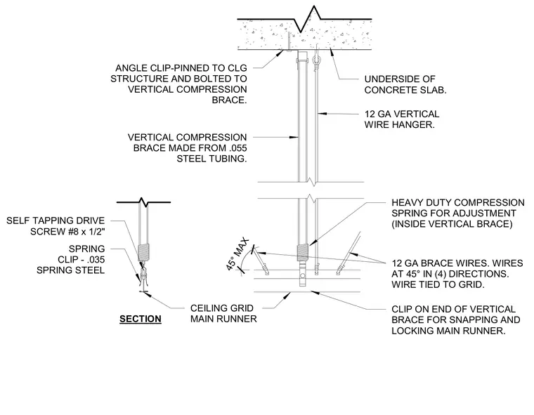
An angle clip is pinned to the underside of the concrete slab structure and bolted to a vertical compression brace made from point zero five five steel tubing. A heavy duty compression spring is housed inside the vertical brace for adjustment. Twelve gauge brace wires run at forty five degree angles in four directions and tie into the ceiling grid. A zero point zero three five spring steel clip connects the vertical brace to the ceiling grid main runner using an eight by one half inch self-tapping drive screw.
12 GA VERTICAL WIRE HANGER. CLIP ON END OF VERTICAL BRACE FOR SNAPPING AND LOCKING MAIN RUNNER. 12 GA BRACE WIRES. WIRES AT 45° IN (4) DIRECTIONS. WIRE TIED TO GRID. UNDERSIDE OF CONCRETE SLAB. HEAVY DUTY COMPRESSION SPRING FOR ADJUSTMENT (INSIDE VERTICAL BRACE) SECTION CEILING GRID MAIN RUNNER ANGLE CLIP-PINNED TO CLG STRUCTURE AND BOLTED TO VERTICAL COMPRESSION BRACE. VERTICAL COMPRESSION BRACE MADE FROM .055 STEEL TUBING. SELF TAPPING DRIVE SCREW #8 x 1/2" SPRING CLIP - .035 SPRING STEEL 45° MAX
Members view this detail in full resolution, download the CAD files (SVG, PDF), and can adapt it in the built-in CAD editor — export DXF, DWG, or PDF.
Start membership