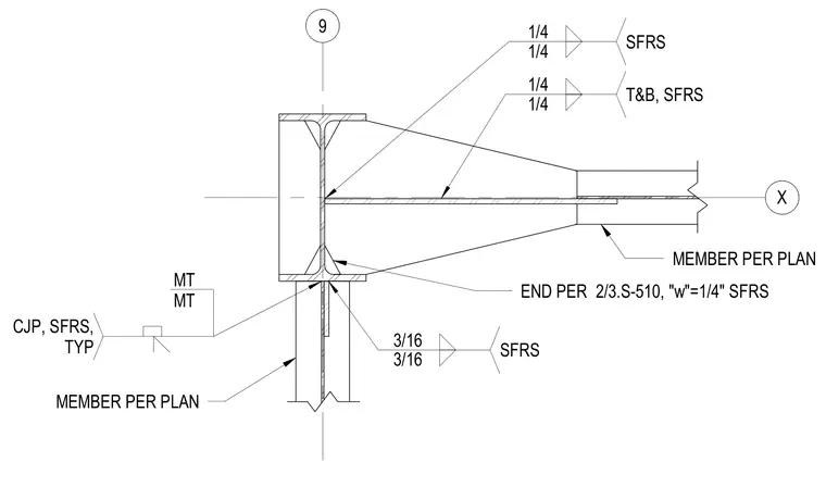
A steel framing connection utilizes a flange plate welded to the column with a one-quarter inch fillet weld at the top and bottom. The horizontal plate extends into a member sized per plan, with end conditions detailed per sheet 2/3.S-510. A vertical member connects below using complete joint penetration welds designated as typical special-force-resisting system elements, supplemented by three-sixteenths inch fillet welds.
X 9 1/4 1/4 T&B, SFRS 1/4 1/4 SFRS END PER 2/3.S-510, "w"=1/4" SFRS MEMBER PER PLAN 3/16 3/16 SFRS CJP, SFRS, TYP MT MT MEMBER PER PLAN
Members view this detail in full resolution, download the CAD files (SVG, PDF), and can adapt it in the built-in CAD editor — export DXF, DWG, or PDF.
Start membership