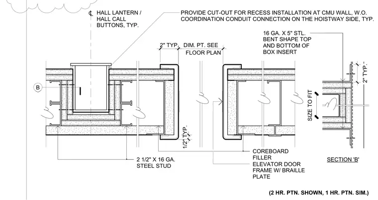
A typical elevator door frame installation within a rated wall partition features a two-hour partition shown and a one-hour partition simulated. The framing utilizes two-and-a-half-inch by sixteen-gauge steel studs with coreboard fillers and sixteen-gauge by five-inch steel bent shapes at the top and bottom of the box insert, sized to fit. A cut-out is provided for recess installation at the CMU wall with wire-opening coordination and a conduit connection on the hoistway side. A braille plate and hall lantern or hall call buttons are integrated into the frame assembly.
2" TYP. ELEVATOR DOOR FRAME W/ BRAILLE PLATE HALL LANTERN / HALL CALL BUTTONS, TYP. 1/2" TYP. DIM. PT. SEE FLOOR PLAN 2 1/2" X 16 GA. STEEL STUD COREBOARD FILLER B SECTION 'B' 16 GA. X 5" STL. BENT SHAPE TOP AND BOTTOM OF BOX INSERT SIZE TO FIT 2" TYP. (2 HR. PTN. SHOWN, 1 HR. PTN. SIM.) PROVIDE CUT-OUT FOR RECESS INSTALLATION AT CMU WALL, W.O. COORDINATION CONDUIT CONNECTION ON THE HOISTWAY SIDE, TYP.
Members view this detail in full resolution, download the CAD files (SVG, PDF), and can adapt it in the built-in CAD editor — export DXF, DWG, or PDF.
Start membership