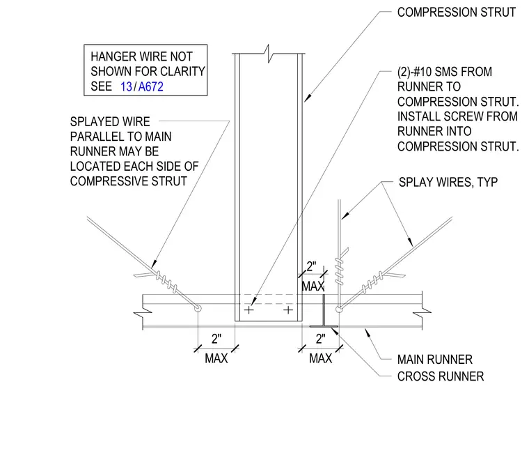
Two number ten sheet metal screws fasten the ceiling grid runner directly to the compression strut. Splayed wires run parallel to the main runner on each side of the compressive strut with a maximum two-inch spacing. Hanger wires are omitted for clarity but referenced to sheet A672 detail 13. Typical splayed wires provide lateral seismic bracing for the suspended ceiling grid.
MAIN RUNNER CROSS RUNNER MAX 2" MAX 2" SPLAY WIRES, TYP (2)-#10 SMS FROM RUNNER TO COMPRESSION STRUT. INSTALL SCREW FROM RUNNER INTO COMPRESSION STRUT. COMPRESSION STRUT HANGER WIRE NOT SHOWN FOR CLARITY SEE SPLAYED WIRE PARALLEL TO MAIN RUNNER MAY BE LOCATED EACH SIDE OF COMPRESSIVE STRUT MAX 2" / 13 A672
Members view this detail in full resolution, download the CAD files (SVG, PDF), and can adapt it in the built-in CAD editor — export DXF, DWG, or PDF.
Start membership