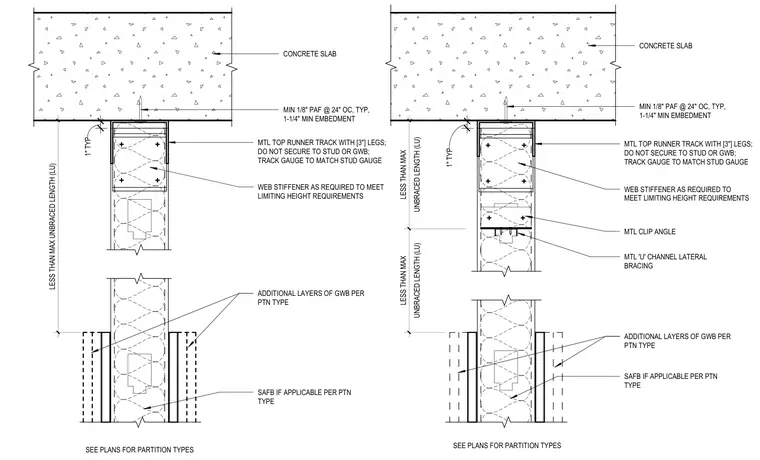
Non-composite fully braced connection between a metal stud partition head and an overhead concrete slab. The metal top runner track features three-inch legs and is attached to the concrete slab using minimum one-eighth-inch powder-actuated fasteners spaced at twenty-four inches on center with a one-and-one-quarter-inch minimum embedment, left unsecured to the stud or gypsum wallboard with a one-inch typical clearance. Web stiffeners are added as required to meet limiting height requirements, alongside optional sound attenuation fire blanket insulation and additional layers of gypsum wallboard per the partition type. A metal U-channel lateral bracing and metal clip angle are integrated in the braced condition to keep the unbraced length less than the maximum allowable unbraced length.
CONCRETE SLAB SEE PLANS FOR PARTITION TYPES ADDITIONAL LAYERS OF GWB PER PTN TYPE SAFB IF APPLICABLE PER PTN TYPE WEB STIFFENER AS REQUIRED TO MEET LIMITING HEIGHT REQUIREMENTS MIN 1/8" PAF @ 24" OC, TYP, 1-1/4" MIN EMBEDMENT LESS THAN MAX UNBRACED LENGTH (LU) MTL TOP RUNNER TRACK WITH [3"] LEGS; DO NOT SECURE TO STUD OR GWB; TRACK GAUGE TO MATCH STUD GAUGE 1" TYP CONCRETE SLAB MIN 1/8" PAF @ 24" OC, TYP, 1-1/4" MIN EMBEDMENT SEE PLANS FOR PARTITION TYPES ADDITIONAL LAYERS OF GWB PER PTN TYPE SAFB IF APPLICABLE PER PTN TYPE UNBRACED LENGTH (LU) LESS THAN MAX UNBRACED LENGTH (LU) LESS THAN MAX WEB STIFFENER AS REQUIRED TO MEET LIMITING HEIGHT REQUIREMENTS MTL 'U' CHANNEL LATERAL BRACING MTL CLIP ANGLE MTL TOP RUNNER TRACK WITH [3"] LEGS; DO NOT SECURE TO STUD OR GWB; TRACK GAUGE TO MATCH STUD GAUGE 1" TYP
Members view this detail in full resolution, download the CAD files (SVG, PDF), and can adapt it in the built-in CAD editor — export DXF, DWG, or PDF.
Start membership