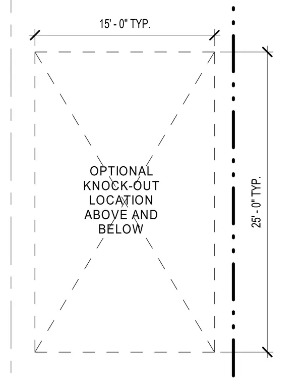
An optional knock-out location layout is defined by twenty-five-foot and fifteen-foot typical dimensional increments relative to a grid or reference line. Dashed boundary lines indicate the perimeter of the opening, marked with diagonal crossing lines and the text note reading optional knock-out location above and below.
25' - 0" TYP. 15' - 0" TYP. OPTIONAL KNOCK-OUT LOCATION ABOVE AND BELOW
Members view this detail in full resolution, download the CAD files (SVG, PDF), and can adapt it in the built-in CAD editor — export DXF, DWG, or PDF.
Start membership