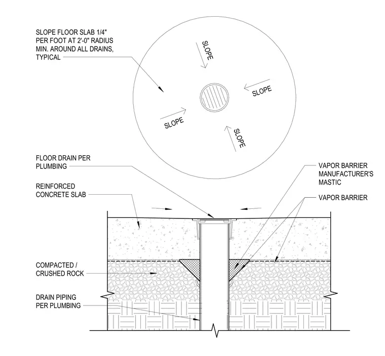
The floor drain assembly sits within a reinforced concrete slab, with the drain body installed per plumbing specifications. The concrete slab slopes at one-quarter inch per foot for a minimum two-foot radius around the drain to ensure positive drainage. A vapor barrier remains beneath the slab and seals to the drain body using the manufacturer's specified mastic. The drain piping extends through the compacted or crushed rock sub-base, with the drain body supported by the surrounding slab and sub-base materials.
FLOOR DRAIN PER PLUMBING REINFORCED CONCRETE SLAB VAPOR BARRIER MANUFACTURER'S MASTIC VAPOR BARRIER DRAIN PIPING PER PLUMBING SLOPE FLOOR SLAB 1/4" PER FOOT AT 2'-0" RADIUS MIN. AROUND ALL DRAINS, TYPICAL SLOPE SLOPE SLOPE SLOPE COMPACTED / CRUSHED ROCK
Members view this detail in full resolution, download the CAD files (SVG, PDF), and can adapt it in the built-in CAD editor — export DXF, DWG, or PDF.
Start membership