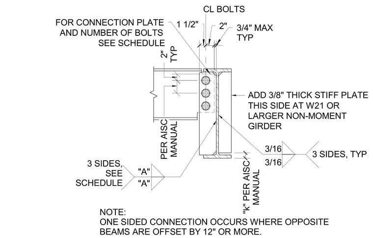
A supported steel beam connects to the web of a supporting girder via a bolted shear tab welded to the girder flange. A three-eighths-inch thick stiffener plate is added to this side at W21 or larger non-moment girders, welded with three-sixteenths-inch fillet welds on three sides as specified in the schedule. Connection plates and the number of bolts are sized per the AISC manual and project schedule, maintaining standard clearances and edge distances including a two-inch typical dimension and three-fourths-inch maximum spacing. A one-sided connection occurs where opposite beams are offset by twelve inches or more.
PER AISC MANUAL 2" TYP 2" 3/4" MAX TYP "k" PER AISC MANUAL 1 1/2" NOTE: ONE SIDED CONNECTION OCCURS WHERE OPPOSITE BEAMS ARE OFFSET BY 12" OR MORE. FOR CONNECTION PLATE AND NUMBER OF BOLTS SEE SCHEDULE CL BOLTS ADD 3/8" THICK STIFF PLATE THIS SIDE AT W21 OR LARGER NON-MOMENT GIRDER "A" "A" SCHEDULE 3 SIDES, SEE 3/16 3 SIDES, TYP 3/16
Members view this detail in full resolution, download the CAD files (SVG, PDF), and can adapt it in the built-in CAD editor — export DXF, DWG, or PDF.
Start membership