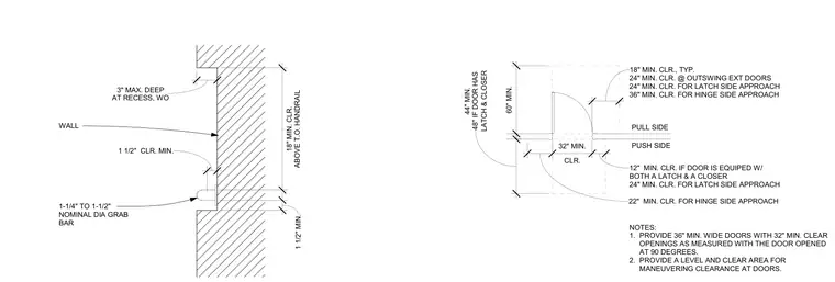
This drawing outlines the required dimensional clearances for architectural accessibility at doors and grab bars. The grab bar assembly requires a one-and-a-quarter to one-and-a-half-inch nominal diameter bar mounted with a one-and-a-half-inch minimum clearance from the wall, positioned eighteen inches minimum above the top of the handrail, and within a wall recess limited to three inches maximum depth. Door maneuvering clearances detail pull side and push side approaches requiring thirty-six inches minimum door width with thirty-two inches minimum clear opening, alongside latch and hinge side approach clearances ranging from twelve to sixty inches depending on hardware configurations such as latches and closers.
BOTH A LATCH & A CLOSER 24" MIN. CLR. FOR LATCH SIDE APPROACH NOTES: 1. PROVIDE 36" MIN. WIDE DOORS WITH 32" MIN. CLEAR OPENINGS AS MEASURED WITH THE DOOR OPENED AT 90 DEGREES. 2. PROVIDE A LEVEL AND CLEAR AREA FOR MANEUVERING CLEARANCE AT DOORS. PULL SIDE PUSH SIDE 24" MIN. CLR. @ OUTSWING EXT DOORS 24" MIN. CLR. FOR LATCH SIDE APPROACH 36" MIN. CLR. FOR HINGE SIDE APPROACH 60" MIN. LATCH & CLOSER 44" MIN. 48" IF DOOR HAS 18" MIN. CLR., TYP. 22" MIN. CLR. FOR HINGE SIDE APPROACH CLR. 32" MIN. 12" MIN. CLR. IF DOOR IS EQUIPED W/ WALL 1-1/4" TO 1-1/2" NOMINAL DIA GRAB BAR 1 1/2" CLR. MIN. ABOVE T.O. HANDRAIL 18" MIN. CLR. AT RECESS, WO 3" MAX. DEEP 1 1/2" MIN.
Members view this detail in full resolution, download the CAD files (SVG, PDF), and can adapt it in the built-in CAD editor — export DXF, DWG, or PDF.
Start membership