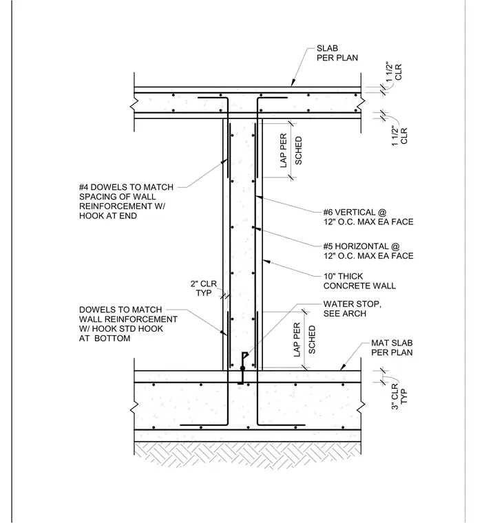
This reinforced concrete wall assembly details the intersection between a mat slab foundation and an upper suspended slab. The ten-inch thick concrete wall is reinforced with number six vertical bars at twelve inches on center maximum on each face and number five horizontal bars at twelve inches on center maximum on each face, maintaining a typical two-inch clear cover. Number four dowels matching the wall reinforcement spacing with standard hooks tie the wall into the bottom mat slab. Similar dowels with hooks at the end connect the top of the wall to the suspended slab per schedule lap requirements. A water stop is provided as detailed in the architectural drawings.
TYP 3" CLR CLR 1 1/2" SCHED LAP PER SCHED LAP PER TYP 2" CLR SLAB PER PLAN #6 VERTICAL @ 12" O.C. MAX EA FACE #5 HORIZONTAL @ 12" O.C. MAX EA FACE 10" THICK CONCRETE WALL DOWELS TO MATCH WALL REINFORCEMENT W/ HOOK STD HOOK AT BOTTOM #4 DOWELS TO MATCH SPACING OF WALL REINFORCEMENT W/ HOOK AT END MAT SLAB PER PLAN CLR 1 1/2" WATER STOP, SEE ARCH
Members view this detail in full resolution, download the CAD files (SVG, PDF), and can adapt it in the built-in CAD editor — export DXF, DWG, or PDF.
Start membership