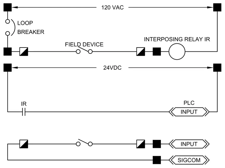
An electrical schematic diagram details the wiring configuration for an interposing relay IR operating between a field device, a programmable logic controller PLC input, and a Sigcom signal input. The control circuit incorporates a loop breaker, a 120 VAC power source, and a 24VDC control loop. Terminals connect the field device contacts through the interposing relay IR to isolate control voltages and trigger the PLC input.
120 VAC 24VDC LOOP BREAKER FIELD DEVICE SIGCOM INPUT INPUT IR PLC INTERPOSING RELAY IR
Members view this detail in full resolution, download the CAD files (SVG, PDF), and can adapt it in the built-in CAD editor — export DXF, DWG, or PDF.
Start membership