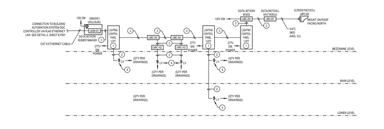
The riser diagram details the lighting control system architecture, showing connections from the building automation system DDC controller via RJ45 Ethernet LAN to the LMSM-ENC1 enclosure and digital network segment manager LMSM-201. Lighting control panels LCP1, LCP2, and LCP3 are connected via digital network bridges LMBC-300 and room controllers LMRC-102. An outdoor photocell LMPO-200 is mounted on the roof facing north, routed with a three-quarter-inch conduit containing three number twenty American Wire Gauge copper conductors to a digital photocell input module LMIO-301. Emergency power at two hundred seventy-seven volts and one hundred twenty volts emergency power feeds are indicated throughout the mezzanine, main, and lower levels, with low-voltage wiring quantities specified per drawings.
Members view this detail in full resolution, download the CAD files (SVG, PDF), and can adapt it in the built-in CAD editor — export DXF, DWG, or PDF.
Start membership