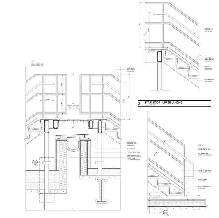
A roof stair expansion joint assembly at an upper landing features a one-foot nominal joint width centered between structural steel supports. The assembly incorporates four-by-eight-inch hollow structural section tubes and eight-by-six-by-one-half-inch steel angles supporting galvanized bar grated pans with closed risers. A mechanical stair expansion joint spanning the break is mechanically fastened to both stairs, supplemented by pipe handrails and guardrails painted with designated finishes. All welds are specified to be ground smooth and painted typically.
PIPE HANDRAIL AND GUARDRAIL PAINTED CO02 NOTE: 1. GRIND SMOOTH AND PAINT ALL WELDS, TYP. STEEL STRINGER, PAINTED CO02 GALVANIZED BAR GRATED PAN WITH CLOSED RISER 21" MAX. 21" MAX. 7" RF1 ________ ________ TYP 11 A5.600 PROVIDE CONTRASTING STAIR NOSING 2" STEEL STRINGER, PAINTED CO02 GALVANIZED BAR GRATED PAN WITH CLOSED RISER PIPE HANDRAIL AND GUARDRAIL PAINTED PT04 30" MIN. 3' - 6" PROVIDE CONTRASTING STAIR NOSING 2" GALVANIZED BAR GRATED PAN WITH CLOSED RISER NOMINAL JOINT WIDTH 1'-0" EQ EQ 1'-0" MIN 2'-5" 30" MIN 3'-6" PIPE HANDRAIL AND GUARDRAIL PAINTED CO02 NOTE: 1. GRIND SMOOTH AND PAINT ALL WELDS, TYP. 4" x 8" HSS TUBE 8" x 6" x 1/2" STEEL ANGLE STAIR EXPANSION JOINT MECHANICALLY FASTENED TO BOTH STAIRS B.O.D.: INPRO 787-A01-300 ________ ________ TYP 11 A5.600 1" 21" MAX 21" MAX SCALE: 1 1/2" = 1'-0" STAIR, ROOF - UPPER LANDING 3
Members view this detail in full resolution, download the CAD files (SVG, PDF), and can adapt it in the built-in CAD editor — export DXF, DWG, or PDF.
Start membership