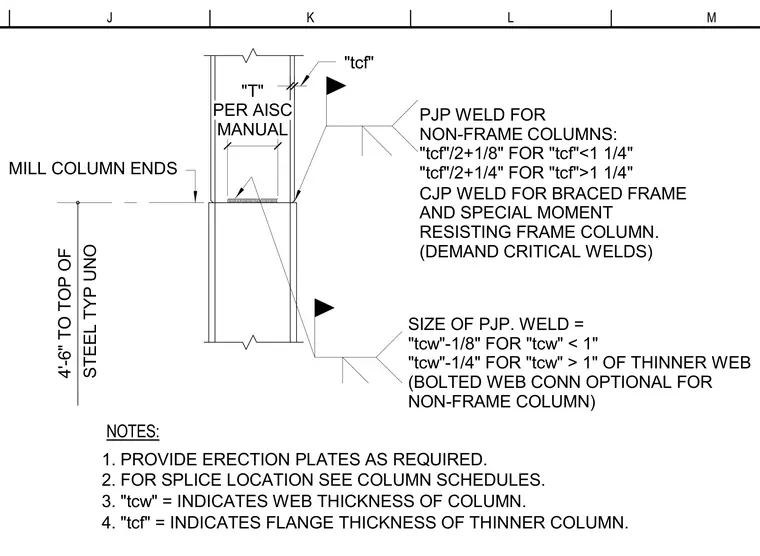
A typical steel column splice connection features milled column ends positioned four feet six inches to the top of steel typically unless otherwise noted. Erection plates are provided as required, with splice locations coordinated per column schedules. Flange connections utilize partial-joint-penetration groove welds for non-frame columns based on flange thickness, and complete-joint-penetration groove welds designated as demand critical for braced frames and special moment-resisting frames. Web connections specify partial-joint-penetration groove weld sizes based on the web thickness of the thinner column, with an optional bolted web connection available for non-frame columns.
"T" PER AISC MANUAL "tcf" NOTES: 1. PROVIDE ERECTION PLATES AS REQUIRED. MILL COLUMN ENDS 4'-6" TO TOP OF STEEL TYP UNO 2. FOR SPLICE LOCATION SEE COLUMN SCHEDULES. 3. "tcw" = INDICATES WEB THICKNESS OF COLUMN. 4. "tcf" = INDICATES FLANGE THICKNESS OF THINNER COLUMN. PJP WELD FOR NON-FRAME COLUMNS: "tcf"/2+1/8" FOR "tcf"<1 1/4" "tcf"/2+1/4" FOR "tcf">1 1/4" CJP WELD FOR BRACED FRAME AND SPECIAL MOMENT RESISTING FRAME COLUMN. (DEMAND CRITICAL WELDS) SIZE OF PJP. WELD = "tcw"-1/8" FOR "tcw" < 1" "tcw"-1/4" FOR "tcw" > 1" OF THINNER WEB (BOLTED WEB CONN OPTIONAL FOR NON-FRAME COLUMN) M L K J
Members view this detail in full resolution, download the CAD files (SVG, PDF), and can adapt it in the built-in CAD editor — export DXF, DWG, or PDF.
Start membership