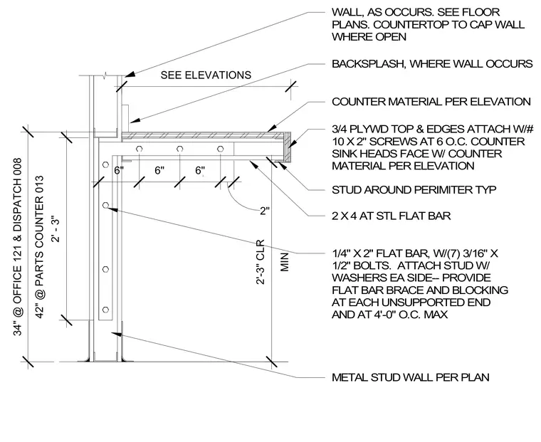
This casework section details a counter assembly anchored against a metal stud wall. The countertop consists of three-quarter-inch plywood for the top and edges, attached with number ten by two-inch screws at six inches on center with countersunk heads finished flush with the counter material. A two-by-four wood member backs a steel flat bar measuring one-quarter by two inches, secured with seven three-sixteenth by one-half-inch bolts and washers on each side. Flat bar bracing and blocking are provided at each unsupported end and spaced at four feet on center maximum. The wall assembly incorporates perimeter studs and maintains a minimum clearance height of two feet three inches.
BACKSPLASH, WHERE WALL OCCURS COUNTER MATERIAL PER ELEVATION 3/4 PLYWD TOP & EDGES ATTACH W/# 10 X 2" SCREWS AT 6 O.C. COUNTER SINK HEADS FACE W/ COUNTER MATERIAL PER ELEVATION STUD AROUND PERIMITER TYP 2 X 4 AT STL FLAT BAR 1/4" X 2" FLAT BAR, W/(7) 3/16" X 1/2" BOLTS. ATTACH STUD W/ WASHERS EA SIDE-- PROVIDE FLAT BAR BRACE AND BLOCKING AT EACH UNSUPPORTED END AND AT 4'-0" O.C. MAX METAL STUD WALL PER PLAN 6" 6" 6" 2" SEE ELEVATIONS 2' - 3" MIN 2'-3" CLR WALL, AS OCCURS. SEE FLOOR PLANS. COUNTERTOP TO CAP WALL WHERE OPEN 42" @ PARTS COUNTER 013 34" @ OFFICE 121 & DISPATCH 008
Members view this detail in full resolution, download the CAD files (SVG, PDF), and can adapt it in the built-in CAD editor — export DXF, DWG, or PDF.
Start membership