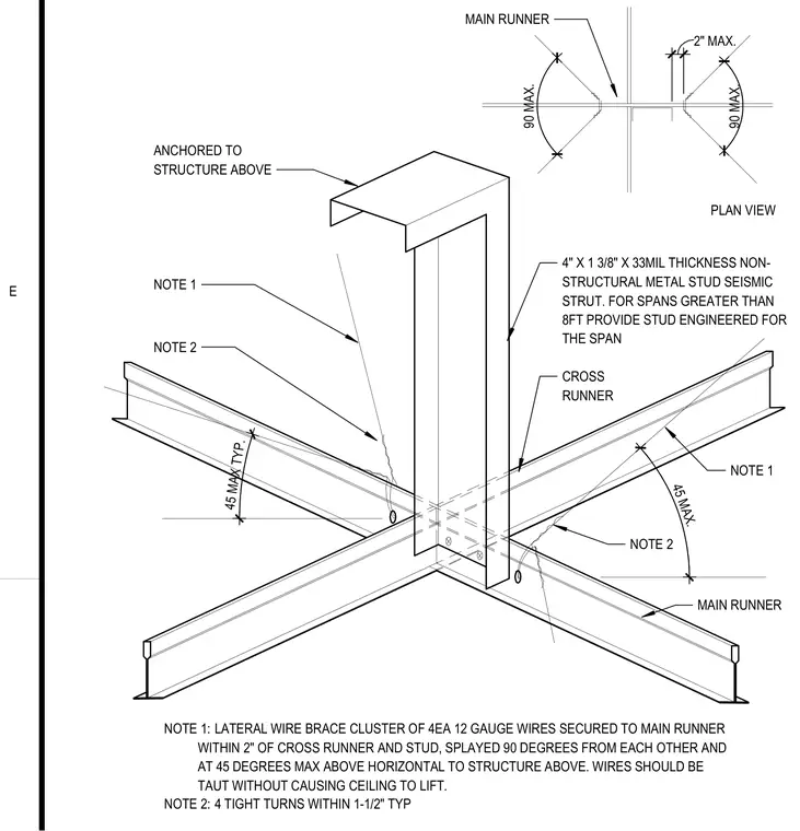
A seismic strut assembly for a suspended ceiling grid features a four-inch by one and three-eighths-inch by thirty-three mil thickness non-structural metal stud acting as a seismic strut anchored to the structure above. A cluster of four twelve-gauge lateral wires secures to the main runner within two inches of the cross runner and stud, splayed ninety degrees from each other and at a maximum of forty-itude degrees above horizontal. The bracing wires must remain taut without lifting the ceiling, utilizing four tight turns within one and one-half inches typical. Spans greater than eight feet require a stud engineered specifically for the span.
NOTE 1: LATERAL WIRE BRACE CLUSTER OF 4EA 12 GAUGE WIRES SECURED TO MAIN RUNNER WITHIN 2" OF CROSS RUNNER AND STUD, SPLAYED 90 DEGREES FROM EACH OTHER AND AT 45 DEGREES MAX ABOVE HORIZONTAL TO STRUCTURE ABOVE. WIRES SHOULD BE TAUT WITHOUT CAUSING CEILING TO LIFT. MAIN RUNNER CROSS RUNNER 4" X 1 3/8" X 33MIL THICKNESS NON- STRUCTURAL METAL STUD SEISMIC STRUT. FOR SPANS GREATER THAN 8FT PROVIDE STUD ENGINEERED FOR THE SPAN NOTE 2 NOTE 1 NOTE 2 NOTE 1 PLAN VIEW ANCHORED TO STRUCTURE ABOVE MAIN RUNNER 4 5 M A X . 4 5 M A X T Y P . 9 0 M A X . 9 0 M A X . 2 " M A X . NOTE 2: 4 TIGHT TURNS WITHIN 1-1/2" TYP E
Members view this detail in full resolution, download the CAD files (SVG, PDF), and can adapt it in the built-in CAD editor — export DXF, DWG, or PDF.
Start membership