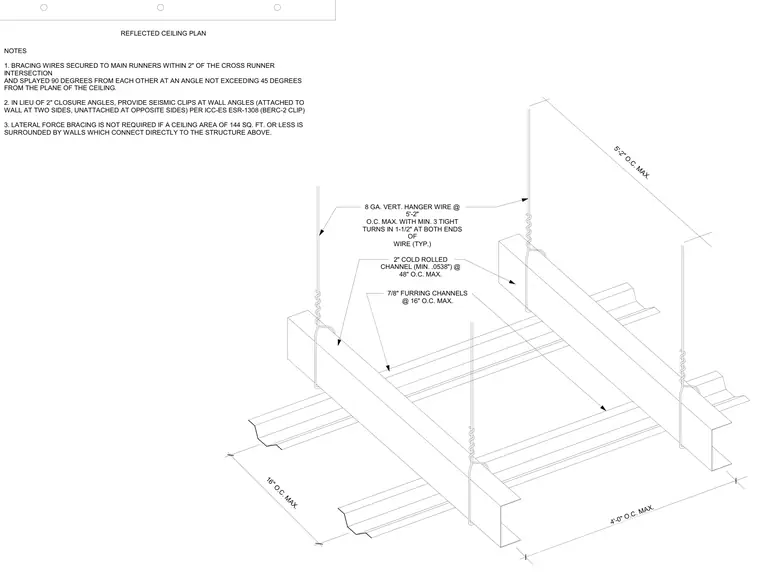
The ceiling framing assembly consists of two-inch cold-rolled channels spaced at a maximum of forty-eight inches on center, suspended by eight-gauge vertical hanger wires spaced at a maximum of five feet two inches on center with a minimum of three tight turns at both ends. Seven-eighth-inch furring channels run perpendicular beneath the cold-rolled channels at a maximum of sixteen inches on center. Bracing wires are secured to main runners within two inches of cross-runner intersections and splayed ninety degrees from each other at an angle not exceeding forty-five degrees from the plane of the ceiling. Seismic clips are provided at wall angles in lieu of two-inch closure angles per ICC-ES ESR-1308 when required.
8 GA. VERT. HANGER WIRE @ 5'-2" O.C. MAX. WITH MIN. 3 TIGHT TURNS IN 1-1/2" AT BOTH ENDS OF WIRE (TYP.) 5'-2" O.C. MAX. 4'-0" O.C. MAX. 16" O.C. MAX. 2" COLD ROLLED CHANNEL (MIN. .0538") @ 48" O.C. MAX. 7/8" FURRING CHANNELS @ 16" O.C. MAX. NOTES 1. BRACING WIRES SECURED TO MAIN RUNNERS WITHIN 2" OF THE CROSS RUNNER INTERSECTION AND SPLAYED 90 DEGREES FROM EACH OTHER AT AN ANGLE NOT EXCEEDING 45 DEGREES FROM THE PLANE OF THE CEILING. 2. IN LIEU OF 2" CLOSURE ANGLES, PROVIDE SEISMIC CLIPS AT WALL ANGLES (ATTACHED TO WALL AT TWO SIDES, UNATTACHED AT OPPOSITE SIDES) PER ICC-ES ESR-1308 (BERC-2 CLIP) 3. LATERAL FORCE BRACING IS NOT REQUIRED IF A CEILING AREA OF 144 SQ. FT. OR LESS IS SURROUNDED BY WALLS WHICH CONNECT DIRECTLY TO THE STRUCTURE ABOVE. REFLECTED CEILING PLAN
Members view this detail in full resolution, download the CAD files (SVG, PDF), and can adapt it in the built-in CAD editor — export DXF, DWG, or PDF.
Start membership