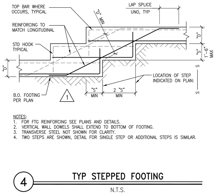
A typical concrete stepped footing assembly incorporates lap splices, standard hooks, and stepped reinforcing bars matching the longitudinal steel. Bottom of footing elevation is set per plan with variable step dimensions denoted as S minimum and 2S minimum. Top bars occur typically where indicated, with vertical wall dowels extending to the bottom of the footing. Transverse steel is omitted for clarity and single or additional steps follow a similar configuration.
Members view this detail in full resolution, download the CAD files (SVG, PDF), and can adapt it in the built-in CAD editor — export DXF, DWG, or PDF.
Start membership