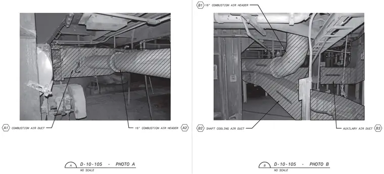
Two photographic views show mechanical air distribution systems routing through structural framing. Photo A highlights a combustion air duct connected to a sixteen-inch combustion air header. Photo B captures a shaft cooling air duct, an auxiliary air duct, and a sixteen-inch combustion air header passing through building columns and overhead piping.
B1)16" COMBUSTION AIR HEADER f TS f A \ -- V/ v - f/^ /7/. n \ ' C; - i V , ClA«P)T ;I/O # I l & 1 | - <£> ( b 2) shaft cooling air duct AUXILARY AIR DUCT ^53) 16“ COMBUSTION AIR HEADER \A2 COMBUSTION AIR DUCT D-10-105 NO SCALE D -10-105 NO SCALE PHOTO A PHOTO B
Members view this detail in full resolution, download the CAD files (SVG, PDF), and can adapt it in the built-in CAD editor — export DXF, DWG, or PDF.
Start membership