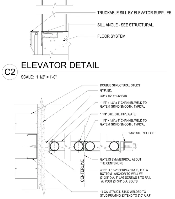
This elevator landing assembly features a one-and-one-quarter-inch standard steel pipe gate supported by one-and-a-half-inch square rail posts and hung with three-and-a-half-inch by three-and-a-half-inch spring hinges at the top and bottom. The gate is anchored to the wall using three three-eighths-inch-diameter by three-inch lag screws and connected to the rail post with three three-eighths-inch-diameter bolts through one-and-a-half-inch by one-eighth-inch by four-inch welded channels ground smooth. The surrounding wall is framed with double structural studs and gypsum board, featuring fourteen-gauge structural studs welded to the framing and extending to three feet above the finished floor. The upper section integrates a truckable sill provided by the elevator supplier, a sill angle sized per structural requirements, and a floor system.
TRUCKABLE SILL BY ELEVATOR SUPPLIER. SILL ANGLE - SEE STRUCTURAL. FLOOR SYSTEM 14 GA. STRUCT. STUD WELDED TO STUD FRAMING EXTEND TO 3'-0" A.F.F. 3 1/2" x 3 1/2" SPRING HINGE, TOP & BOTTOM. ANCHOR TO WALL W/ (3) 3/8" DIA. 3" LAG SCREWS & TO RAIL W/ POST (3) 3/8" DIA. BOLTS 1 1/2" x 1/8" x 4" CHANNEL WELD TO GATE & GRIND SMOOTH, TYPICAL 1 1/4" STD. STL. PIPE GATE 3/8" x 1/2" x 1'-6" BAR GYP. BD. DOUBLE STRUCTURAL STUDS 1 1/2" x 1/8" x 4" CHANNEL WELD TO GATE & GRIND SMOOTH, TYPICAL 1-1/2" SQ. RAIL POST GATE IS SYMMETRICAL ABOUT THE CENTERLINE CENTERLINE SCALE: 1 1/2" = 1'-0" C2 ELEVATOR DETAIL
Members view this detail in full resolution, download the CAD files (SVG, PDF), and can adapt it in the built-in CAD editor — export DXF, DWG, or PDF.
Start membership