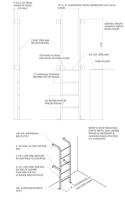
A steel elevator pit ladder is mounted to the elevator pit walls. The assembly utilizes two and a half inch by three-eighths inch steel side rails punched for three-quarter inch diameter rungs welded in place. Two and a half inch by three-eighths inch steel brackets welded to each side rail secure the top of the ladder to the wall using five-eighths inch diameter expansion bolts. Additional five-eighths inch diameter expansion bolts anchor the bottom feet of the ladder to the pit floor. The top rung aligns with the finish floor elevation, maintaining a maximum twelve-inch spacing between rungs and four to four and a half inches of clearance from the inside of the rung to the wall.
COORDINATE w/ ELEVATOR MANF. 1'-4" 5/8" DIA. EXPANSION BOLTS (TYP.) 2 1/2" RAD. AT CEN LINE SIDE RAIL 2 1/2" x 3/8" STEEL BRACKET EA SIDE WELD TO SIDE RAILS 2 1/2" x 3/8" STEEL SIDE RAIL EA SIDE OF LADDER- PUNCHED FOR 3/4" ∅ RUNGS WELD IN PLACE 5/8" ∅ EXPANSION BOLTS (TYP.) 6'-0" 4" TO 4 1/2" FROM INSIDE OF RUNG TO WALL 12" to 16" CLEAR RUNG WIDTH (DEPENDING ON LOCAL CODE) REFER TO SHOP DRAWINGS FOR PIT DEPTH. ADD LADDER RUNGS AS NECESSARY & MAINTAIN EQUAL SPACING (12" MAXIMUM) ALL RUNGS MUST BE SPACED EQUALLY 12" MAXIMUM DISTANCE BETWEEN TOP OF RUNGS TOP RUNG @ SAME ELEVATION AS FINISH FLOOR 2"x5/8" STEEL BAR RECOMMENDED 3/4" DIA. STEEL BAR FINISH FLOOR SIDE RAIL HEIGHT MINIMUM ABOVE FINISH FLOOR
Members view this detail in full resolution, download the CAD files (SVG, PDF), and can adapt it in the built-in CAD editor — export DXF, DWG, or PDF.
Start membership