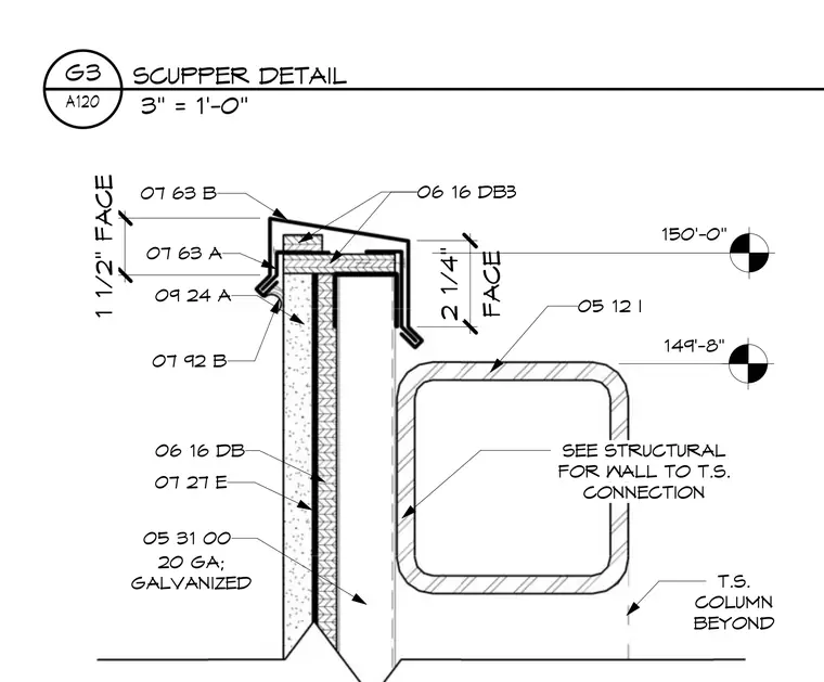
A roof drainage penetration passes through a parapet wall adjacent to a structural steel tube column. The assembly incorporates a twenty-gauge galvanized metal scupper liner, sheathing, and flashing elements indexed with standard MasterFormat specification callouts. Vertical dimensions indicate a one-and-one-half-inch face on the exterior side and a two-and-one-quarter-inch face on the interior side. A hollow structural section column is nearby with an elevation note directing to structural drawings for the wall-to-tube-steel connection. The parapet construction includes waterproofing and exterior finish layers coordinated with the drainage path.
09 24 A 07 27 E 06 16 DB 07 92 B 07 63 A 07 63 B 1 1/2" FACE FACE 2 1/4" 06 16 DB 06 16 DB SEE STRUCTURAL FOR WALL TO T.S. CONNECTION 05 12 I 150'-0" 149'-8" T.S. COLUMN BEYOND 05 31 00 20 GA; GALVANIZED 3" = 1'-0" A120 G3 SCUPPER DETAIL
Members view this detail in full resolution, download the CAD files (SVG, PDF), and can adapt it in the built-in CAD editor — export DXF, DWG, or PDF.
Start membership