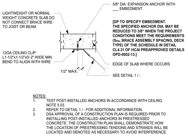
A ceiling seismic brace wire connects to an overhead lightweight or normal weight concrete slab via a five-eighths-inch diameter expansion anchor secured into the concrete, linking a twelve-gauge steel ceiling clip measuring one and one-half by one and one-half inches wide by two inches. The clip is bent to align with the brace wire, which maintains a maximum distance of one-half inch from the anchor. Notes specify that brace wires must not connect directly to joists or beams, and post-installed anchors in prestressed concrete require a construction plan approved by the Division of the State Architect to avoid stressing tendons.
SEE DETAIL 1 / - 5/8" DIA EXPANSION ANCHOR WITH ___ EMBEDMENT 12GA CEILING CLIP: L1-1/2"x1-1/2"x0'-2" WIDE MIN. BEND TO ALIGN WITH WIRE LIGHTWEIGHT OR NORMAL WEIGHT CONCRETE SLAB DO NOT CONNECT BRACE WIRE TO JOIST OR BEAM 1/2" MAX. NOTES: 1. TEST POST-INSTALLED ANCHORS IN ACCORDANCE WITH CEILING NOTE 5.03. 2. REFER TO DETAIL 1 / - FOR ADDITIONAL INFORMATION. 3. DSA APPROVAL OF A CONSTRUCTION PLAN IS REQUIRED PRIOR TO INSTALLING POST-INSTALLED ANCHORS IN PRESTRESSED CONCRETE. THE CONSTRUCTIN PLAN SHALL DEMONSTRATE HOW THE LOCATION OF PRESTRESSING TENDONS AND STRANDS WILL BE LOCATED AND DENOTED AS NECESSARY TO AVOID INTERFERENCE. EDGE OF SLAB WHERE OCCURS [DP TO SPECIFY EMBEDMENT. THE SPECIFIED ANCHOR DIA. MAY BE REDUCED TO 3/8" WHEN THE PROJECT CONDITIONS MEET THE REQUIREMENTS (S DS , BRACE ASSEMBLY SPACING, DECK TYPE) OF THE SCHEDULE IN DETAIL CL4.31 OF HCAI PREAPPROVED DETAILS OPD-0002-13.]
Members view this detail in full resolution, download the CAD files (SVG, PDF), and can adapt it in the built-in CAD editor — export DXF, DWG, or PDF.
Start membership