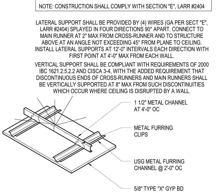
The ceiling assembly consists of five-eighths inch Type X gypsum board fastened to USG metal furring channels spaced at two feet on center. These furring channels attach via metal furring clips to one-and-one-half-inch metal channels spaced at four feet on center. Lateral support is provided by four splayed wires spaced at twelve-foot intervals in each direction, connected to the main runner and the structure above at an angle not exceeding forty-five degrees. Vertical supports comply with IBC requirements and CISCA standards, with additional support required at discontinuous ends near walls.
NOTE: CONSTRUCTION SHALL COMPLY WITH SECTION "E", LARR #2404 LATERAL SUPPORT SHALL BE PROVIDED BY (4) WIRES (GA PER SECT "E", LARR #2404) SPLAYED IN FOUR DIRECTIONS 90° APART. CONNECT TO MAIN RUNNER AT 2" MAX FROM CROSS-RUNNER AND TO STRUCTURE ABOVE AT AN ANGLE NOT EXCEEDING 45° FROM PLANE TO CEILING. INSTALL LATERAL SUPPORTS AT 12'-0" INTERVALS EACH DIRECTION WITH FIRST POINT AT 4'-0" MAX FROM EACH WALL. VERTICAL SUPPORT SHALL BE COMPLIANT WITH REQUIREMENTS OF 2000 IBC 1621.2.5.2.2 AND CISCA 3-4, WITH THE ADDED REQUIREMENT THAT DISCONTINUOUS ENDS OF CROSS-RUNNERS AND MAIN RUNNERS SHALL BE VERTICALLY SUPPORTED AT 8" MAX FROM SUCH DISCONTINUITIES WHICH OCCUR WHERE CEILING IS DISRUPTED BY A WALL. 1 1/2" METAL CHANNEL AT 4'-0" OC METAL FURRING CLIPS USG METAL FURRING CHANNEL @ 2'-0" OC 5/8" TYPE "X" GYP BD
Members view this detail in full resolution, download the CAD files (SVG, PDF), and can adapt it in the built-in CAD editor — export DXF, DWG, or PDF.
Start membership