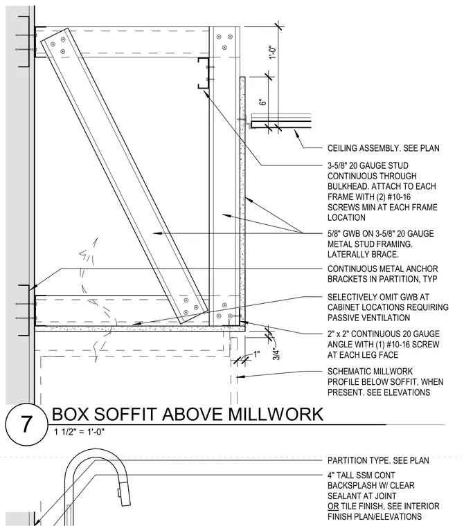
This interior architectural detail shows a box soffit framed with three-and-five-eighths-inch twenty-gauge metal studs, clad with five-eighths-inch gypsum wallboard, and laterally braced as detailed. A continuous two-by-two-inch twenty-gauge metal angle attaches with one number ten-sixteen screw at each leg face, while a continuous three-and-five-eighths-inch twenty-gauge stud runs through the bulkhead and fastens to each frame with a minimum of two number ten-sixteen screws at each frame location. Gypsum wallboard is selectively omitted at cabinet locations requiring passive ventilation, positioned above millwork with a schematic profile and a four-inch tall solid surface material continuous backsplash with clear sealant at the joint or tile finish.
PARTITION TYPE. SEE PLAN 4" TALL SSM CONT BACKSPLASH W/ CLEAR SEALANT AT JOINT OR TILE FINISH, SEE INTERIOR FINISH PLAN/ELEVATIONS 3/4" 5/8" GWB ON 3-5/8" 20 GAUGE METAL STUD FRAMING. LATERALLY BRACE. 1" CEILING ASSEMBLY. SEE PLAN SCHEMATIC MILLWORK PROFILE BELOW SOFFIT, WHEN PRESENT. SEE ELEVATIONS 1'-0" 6" 3-5/8" 20 GAUGE STUD CONTINUOUS THROUGH BULKHEAD. ATTACH TO EACH FRAME WITH (2) #10-16 SCREWS MIN AT EACH FRAME LOCATION 2" x 2" CONTINUOUS 20 GAUGE ANGLE WITH (1) #10-16 SCREW AT EACH LEG FACE CONTINUOUS METAL ANCHOR BRACKETS IN PARTITION, TYP SELECTIVELY OMIT GWB AT CABINET LOCATIONS REQUIRING PASSIVE VENTILATION 1 1/2" = 1'-0" 7 BOX SOFFIT ABOVE MILLWORK
Members view this detail in full resolution, download the CAD files (SVG, PDF), and can adapt it in the built-in CAD editor — export DXF, DWG, or PDF.
Start membership