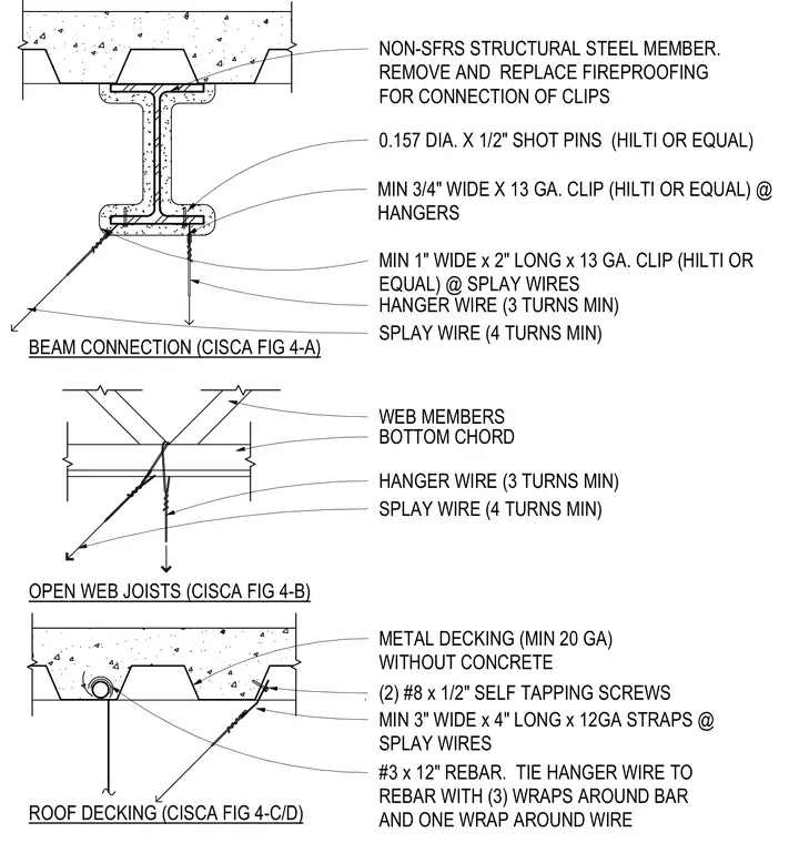
Three methods for attaching seismic hanger and splay wires to overhead structural elements. A non-SFRM structural steel member has fireproofing removed for the connection of minimum three-quarter-inch wide by 13-gauge clips secured with 0.157-inch diameter by half-inch shot-in pins, supporting hanger wires with three minimum turns and splay wires with four minimum turns. Attachment to the bottom chord web members of an open-web joist uses direct wire wraps. A metal roof decking profile without concrete utilizes two number 8 by half-inch self-tapping screws securing a three-inch wide by four-inch long 12-gauge strap for splay wires, and a number 3 by 12-inch rebar tied to the hanger wire with three wraps around the bar and one wrap around the wire.
BEAM CONNECTION (CISCA FIG 4-A) NON-SFRS STRUCTURAL STEEL MEMBER. REMOVE AND REPLACE FIREPROOFING FOR CONNECTION OF CLIPS 0.157 DIA. X 1/2" SHOT PINS (HILTI OR EQUAL) MIN 3/4" WIDE X 13 GA. CLIP (HILTI OR EQUAL) @ HANGERS HANGER WIRE (3 TURNS MIN) SPLAY WIRE (4 TURNS MIN) MIN 1" WIDE x 2" LONG x 13 GA. CLIP (HILTI OR EQUAL) @ SPLAY WIRES OPEN WEB JOISTS (CISCA FIG 4-B) WEB MEMBERS BOTTOM CHORD HANGER WIRE (3 TURNS MIN) SPLAY WIRE (4 TURNS MIN) MIN 3" WIDE x 4" LONG x 12GA STRAPS @ SPLAY WIRES METAL DECKING (MIN 20 GA) WITHOUT CONCRETE ROOF DECKING (CISCA FIG 4-C/D) (2) #8 x 1/2" SELF TAPPING SCREWS #3 x 12" REBAR. TIE HANGER WIRE TO REBAR WITH (3) WRAPS AROUND BAR AND ONE WRAP AROUND WIRE
Members view this detail in full resolution, download the CAD files (SVG, PDF), and can adapt it in the built-in CAD editor — export DXF, DWG, or PDF.
Start membership