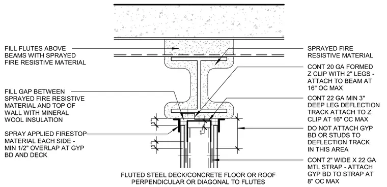
A one-hour fire-resistant partition head assembly occurs beneath a fluted steel deck and concrete floor or roof slab supported by a steel beam. A continuous twenty-gauge formed Z-clip with two-inch legs attaches directly to the bottom flange of the beam at a maximum of sixteen inches on center. A continuous twenty-two-gauge minimum three-inch deep-leg deflection track fastens to the Z-clip at a maximum of sixteen inches on center, leaving an unattached clearance zone where studs and gypsum board remain free from structural deflection loads. Continuous two-inch wide by twenty-two-gauge metal straps secure the gypsum board to the framing at a maximum of eight inches on center. Sprayed fire-resistive material coats the steel beam and fills the flutes above. Mineral wool insulation packs the gap between the fire-resistive material and the top of the wall, supplemented by spray-applied firestop material on each side with a minimum half-inch overlap onto the gypsum board and deck.
1" 1" 1" 4 21/64" CONT 2" WIDE X 22 GA MTL STRAP - ATTACH GYP BD TO STRAP AT 8" OC MAX DO NOT ATTACH GYP BD OR STUDS TO DEFLECTION TRACK IN THIS AREA CONT 22 GA MIN 3" DEEP LEG DEFLECTION TRACK ATTACH TO Z CLIP AT 16" OC MAX CONT 20 GA FORMED Z CLIP WITH 2" LEGS - ATTACH TO BEAM AT 16" OC MAX SPRAYED FIRE RESISTIVE MATERIAL SPRAY APPLIED FIRESTOP MATERIAL EACH SIDE - MIN 1/2" OVERLAP AT GYP BD AND DECK FILL GAP BETWEEN SPRAYED FIRE RESISTIVE MATERIAL AND TOP OF WALL WITH MINERAL WOOL INSULATION FILL FLUTES ABOVE BEAMS WITH SPRAYED FIRE RESISTIVE MATERIAL FLUTED STEEL DECK/CONCRETE FLOOR OR ROOF PERPENDICULAR OR DIAGONAL TO FLUTES
Members view this detail in full resolution, download the CAD files (SVG, PDF), and can adapt it in the built-in CAD editor — export DXF, DWG, or PDF.
Start membership