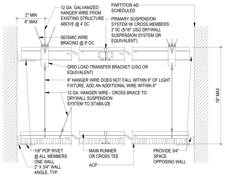
A suspended drywall ceiling framing system is hung from the existing structure above using twelve-gauge galvanized hanger wires spaced at four feet on center with seismic wire bracing installed at eight feet on center. The primary suspension system features main runners and cross tees spaced at two feet on center connected to a grid load transfer bracket, with an additional hanger wire added within six inches of any light fixture if the primary wire does not fall within that range. Twelve-gauge hanger wires are cross-braced to the drywall suspension system for stabilization. The perimeter detail includes a two-inch by three-quarter-inch wall angle secured to one wall with a one-eighth-inch pop rivet at all members and a three-quarter-inch space provided at the opposing wall.
6'' MAX 2'' MIN 18'' MAX 12 GA. GALVANIZED HANGER WIRE FROM EXISTING STRUCTURE ABOVE @ 4' 0C SEISMIC WIRE BRACING @ 8' OC PRIMARY SUSPENSION SYSTEM W/ CROSS MEMBERS 2' 0C (5/16" USG DRYWALL SUSPENSION SYSTEM OR EQUIVALENT) PARTITION AS SCHEDULED GRID LOAD TRANSFER BRACKET (USG OR EQUIVALENT) IF HANGER WIRE DOES NOT FALL WITHIN 6" OF LIGHT FIXTURE, ADD AN ADDITIONAL WIRE WITHIN 6" 12 GA. HANGER WIRE - CROSS BRACE TO DRYWALL SUSPENSION SYSTEM TO STABILIZE 1/8" POP RIVET @ ALL MEMBERS ONE WALL 2" X 3/4" WALL ANGLE, TYP. MAIN RUNNER OR CROSS TEE ACP PROVIDE 3/4" SPACE OPPOSING WALL
Members view this detail in full resolution, download the CAD files (SVG, PDF), and can adapt it in the built-in CAD editor — export DXF, DWG, or PDF.
Start membership