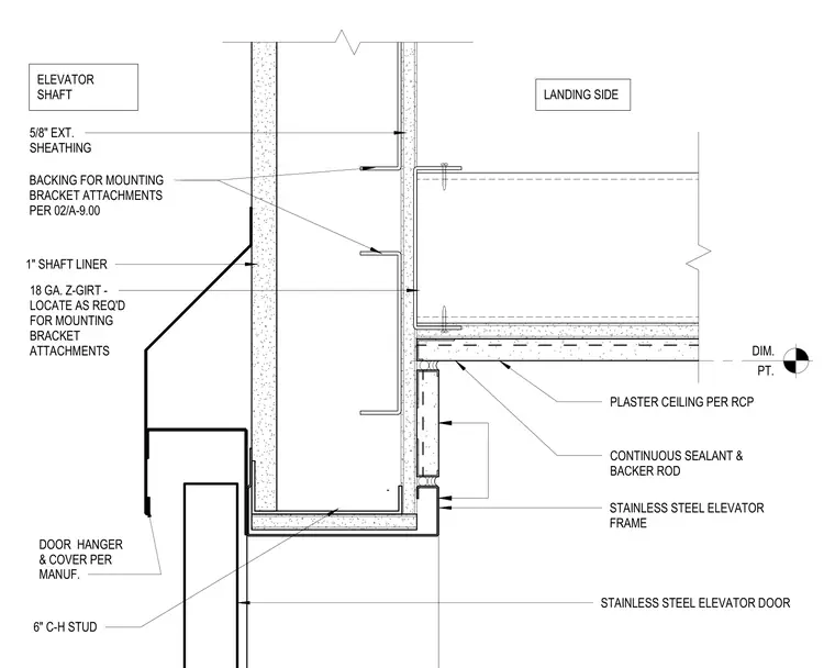
An elevator head and landing side interface at an exterior plaster wall. The assembly features a stainless steel elevator frame and door with a manufacturer-specified door hanger and cover. The shaft wall is constructed with 6-inch C-H studs, 1-inch shaft liner, and 5/8-inch exterior sheathing, supplemented by 18-gauge Z-girts located as required for mounting bracket attachments. A plaster ceiling per the reflected ceiling plan abuts the stainless steel elevator frame, sealed with a continuous sealant and backer rod.
DIM. PT. LANDING SIDE ELEVATOR SHAFT STAINLESS STEEL ELEVATOR DOOR 1" SHAFT LINER 6" C-H STUD 5/8" EXT. SHEATHING CONTINUOUS SEALANT & BACKER ROD STAINLESS STEEL ELEVATOR FRAME PLASTER CEILING PER RCP BACKING FOR MOUNTING BRACKET ATTACHMENTS PER 02/A-9.00 18 GA. Z-GIRT - LOCATE AS REQ'D FOR MOUNTING BRACKET ATTACHMENTS DOOR HANGER & COVER PER MANUF.
Members view this detail in full resolution, download the CAD files (SVG, PDF), and can adapt it in the built-in CAD editor — export DXF, DWG, or PDF.
Start membership