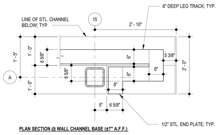
This plan section details a wall channel base assembly positioned at approximately seven inches above finished floor. A six-inch deep leg track frames the wall junction, tied back with a half-inch typical steel end plate. A line of steel channel runs below typical, positioned with detailed dimensional spacing relative to the structural column and track components.
15 A 2' - 10" LINE OF STL. CHANNEL BELOW; TYP. PLAN SECTION @ WALL CHANNEL BASE (±7" A.F.F.) 6 5/8" 1' - 0" 5 3/8" 1' - 0" 6 5/8" 5" 6 5/8" 1' - 5" 2' - 0" 6" DEEP LEG TRACK; TYP. 1/2" STL. END PLATE; TYP. 6" 6" 6" 6"
Members view this detail in full resolution, download the CAD files (SVG, PDF), and can adapt it in the built-in CAD editor — export DXF, DWG, or PDF.
Start membership