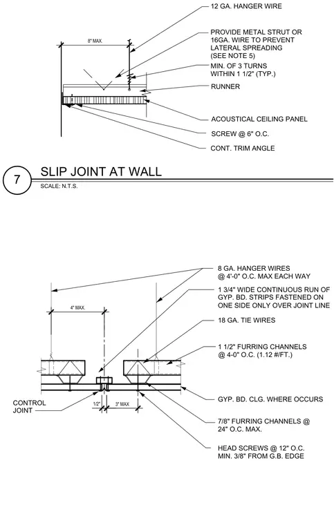
Suspended gypsum board ceiling details showing a control joint assembly and a wall slip joint. The control joint incorporates one-and-three-quarter-inch-wide continuous gypsum board strips fastened on one side only over the joint line, supported by one-and-one-half-inch furring channels at four feet on center maximum each way, eight-gauge hanger wires, and eighteen-gauge tie wires with seven-eighths-inch furring channels at twenty-four inches on center maximum. Head screws are spaced at twelve inches on center with a minimum three-eighths-inch clearance from the gypsum board edge. The wall slip joint features a continuous trim angle secured with screws at six inches on center, twelve-gauge hanger wires with a minimum of three turns within one-and-one-half inches, and a metal strut or sixteen-gauge wire to prevent lateral spreading.
8" MAX. 16GA. WIRE TO PREVENT PROVIDE METAL STRUT OR LATERAL SPREADING 12 GA. HANGER WIRE ACOUSTICAL CEILING PANEL WITHIN 1 1/2" (TYP.) MIN. OF 3 TURNS SCREW @ 6" O.C. CONT. TRIM ANGLE 7 SLIP JOINT AT WALL SCALE: N.T.S. RUNNER (SEE NOTE 5) MIN. 3/8" FROM G.B. EDGE HEAD SCREWS @ 12" O.C. 7/8" FURRING CHANNELS @ 24" O.C. MAX. 1 1/2" FURRING CHANNELS @ 4-0" O.C. (1.12 #/FT.) GYP. BD. CLG. WHERE OCCURS @ 4'-0" O.C. MAX EACH WAY 8 GA. HANGER WIRES 18 GA. TIE WIRES 1/2" 3" MAX 1 3/4" WIDE CONTINUOUS RUN OF GYP. BD. STRIPS FASTENED ON ONE SIDE ONLY OVER JOINT LINE 4" MAX. CONTROL JOINT
Members view this detail in full resolution, download the CAD files (SVG, PDF), and can adapt it in the built-in CAD editor — export DXF, DWG, or PDF.
Start membership