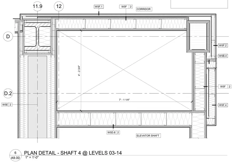
This plan detail shows the architectural framing and wall assembly for elevator shaft four between levels three and fourteen. The partition consists of metal stud framing with gypsum board layers facing the corridor and shaft interior. Structural steel columns and concrete or masonry elements bound the perimeter with specified wall dimensions of four feet two and three-quarter inches by seven feet one and one-quarter inches. Detail callouts reference surrounding wall types and adjacent structural grid lines.
D 12 D.2 11.9 W5F 2 W5D.8 2 W5F 2 W5E 2 W5F.1 W5F.4 CORRIDOR ELEVATOR SHAFT 4' - 2 3/4" 7' - 1 1/4" W5F.2 W5B.4 1" = 1'-0" A9.00 6 PLAN DETAIL - SHAFT 4 @ LEVELS 03-14
Members view this detail in full resolution, download the CAD files (SVG, PDF), and can adapt it in the built-in CAD editor — export DXF, DWG, or PDF.
Start membership