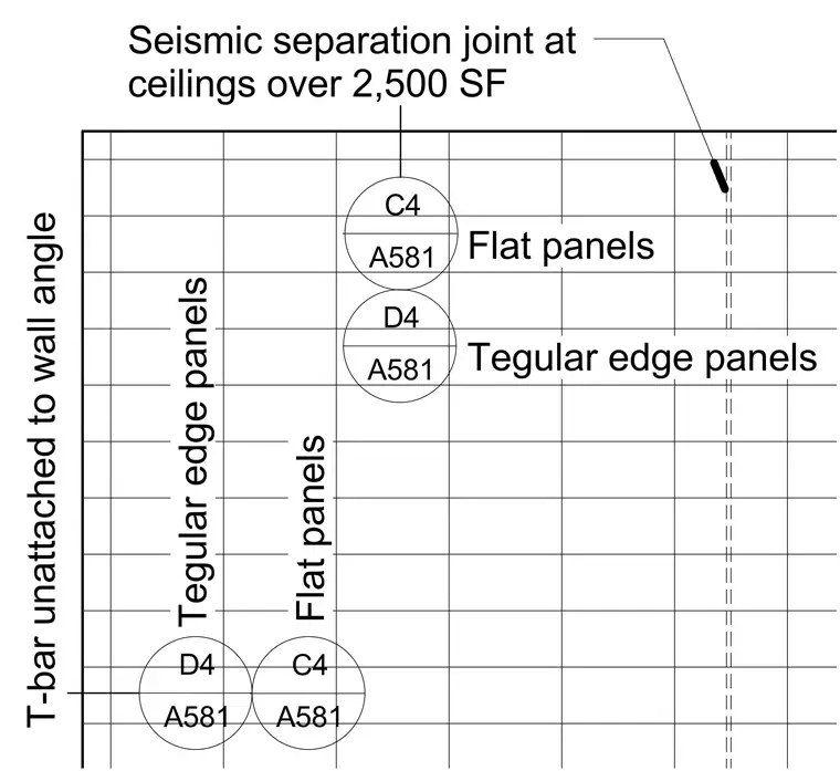
This plan diagram outlines the seismic separation joint requirements for suspended ceilings exceeding two thousand five hundred square feet. The assembly features flat panels and tegular edge panels arranged adjacent to wall angles where the T-bar remains unattached to accommodate movement. Detail callouts designate specific conditions using grid references C4 and D4 on sheet A581. The layout establishes proper clearance and joint placement for interior ceiling seismic design.
T-bar unattached to wall angle Seismic separation joint at ceilings over 2,500 SF D4 A581 C4 A581 D4 A581 C4 A581 Flat panels Tegular edge panels Flat panels Tegular edge panels
Members view this detail in full resolution, download the CAD files (SVG, PDF), and can adapt it in the built-in CAD editor — export DXF, DWG, or PDF.
Start membership