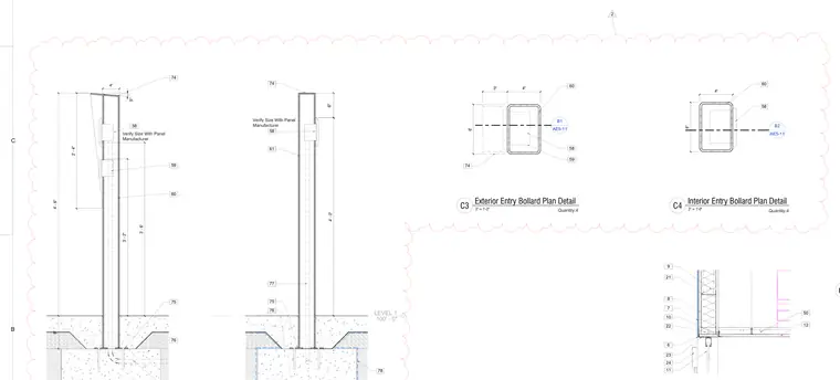
These architectural details illustrate exterior and interior entry bollards with specific dimensional layouts, plan configurations, and foundation anchorage connections. The exterior bollard detail shows a sloped top profile with specified heights, clearances, and mounting dimensions, while the plan views indicate rectangular post profiles with associated callouts. Bollard sizes and clearances are noted to be verified with the panel manufacturer. The assembly embeds into concrete foundations with base plates and anchor bolts.
6 7 8 9 10 11 12 21 22 23 24 50 LEVEL 1 100' - 0" LEVEL 1 100' - 0" 6" 61 58 Verify Size With Panel Manufacturer 4' - 0" 74 75 76 77 78 5° 58 59 60 4" 2' - 4" 4' - 6" 8" 3' - 2" 3' - 6" Verify Size With Panel Manufacturer 74 75 76 B1 AE5-11 3" 4" 60 74 58 59 6" B2 AE5-11 60 58 4" 6" C B C5 3" = 1'-0" C3 Exterior Entry Bollard Plan Detail 2 3" = 1'-0" C4 Interior Entry Bollard Plan Detail Quantity:4 Quantity:4
Members view this detail in full resolution, download the CAD files (SVG, PDF), and can adapt it in the built-in CAD editor — export DXF, DWG, or PDF.
Start membership